A frequency divider, also called a clock divider or scaler or prescaler, is a circuit that takes an input signal of a frequency, fin, and generates an output signal of a frequency :
 |
| Source - Wikipedia |
Where n is an integer (Wikipedia). In this post I explain how to implement the digital design of a simple clock divider(fin/2).
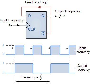 | |||
| Source - ElectronicsTutorials |
Verilog module
 module clock_divider (clk_in, enable,reset, clk_out);
   input clk_in; // input clock
   input reset;
   input enable;
   output clk_out; // output clock

   wire  clk_in;
   wire  enable;

   reg clk_out;

   always @ (posedge clk_in)
     if (reset)
       begin
         clk_out <= 1'b0;
       end
     else if (enable)
       begin
         clk_out <= !clk_out ;
       end

 endmodule
Test-bench
 module tb_clock_divider;
   reg clk_in, reset,enable;
   wire clk_out;

   clock_divider U0 (
    .clk_in (clk_in),
    .enable(enable),
    .reset (reset),
    .clk_out (clk_out)
   );

   initial
     begin
       clk_in = 0;
       reset = 0;
       enable = 1;
       #10 reset = 1;
       #10 reset = 0;
       #100 $finish;
     end

   always #5 clk_in = ~clk_in;

 endmodule
 |
| Simulation results |
 | ||||||||||||||||||
| Elaborated design |
Verilog simulation and RTL analysis was done in Vivado 2014.2. If you want to divide the input frequency further, (fin/4, fin/8, fin/16), you can extend the same circuit as follows.
 |
| Source - ElectronicsTutorials |
Nice article. Keep up the good work bro!!
ReplyDeleteThanks bro :)
Delete